

A growing number of PLC device manufacturers open their ecosystems for third party runtimes and other software components. Some of these devices feature on-board I/O pins, and you can configure your OTee runtime in a way that it can process these signals through the device’s file system or process image directly. Here’s how. In the top bar of your project browser pane, press the “Create an entity” button. Select “Driver configuration” from the drop-down menu in the “Type” field, then select “Direct I/O” from the drop-down menu in the “Driver” field. This will create a Direct I/O node in your project browser tree. Select the node to access the driver configuration.Documentation Index
Fetch the complete documentation index at: https://docs.otee.io/llms.txt
Use this file to discover all available pages before exploring further.
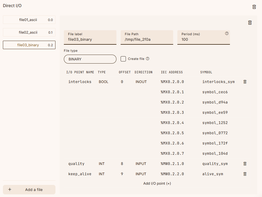
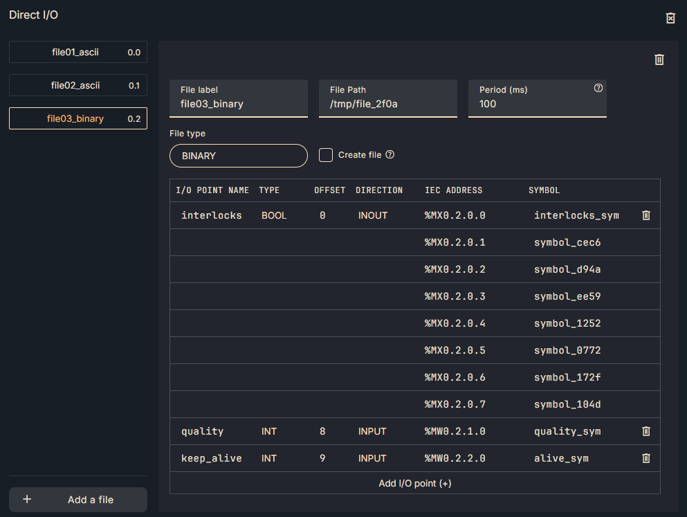 Consult your device manufacturer’s technical documentation to find out how to best map their built-in I/O channels. OTee handles ASCII files (where typically one file represents one I/O channel) and binary files (or process images, where typically all I/O channels are included and separated by a particular offset that needs to be set in the configuration of this driver).
Hit the “Add a file” button to begin your Direct I/O configuration. Per file, there are a few global settings to be chosen:
Consult your device manufacturer’s technical documentation to find out how to best map their built-in I/O channels. OTee handles ASCII files (where typically one file represents one I/O channel) and binary files (or process images, where typically all I/O channels are included and separated by a particular offset that needs to be set in the configuration of this driver).
Hit the “Add a file” button to begin your Direct I/O configuration. Per file, there are a few global settings to be chosen:
| Field Name | Explanation |
|---|---|
| File label | A friendly name for the file to be used. |
| File Path | The absolute file path of the file to be used. |
| Period (ms) | How often the file will be read or modified, in milliseconds. |
| File type | The file type: ASCII or binary. ASCII files are text, whereas binary files are packed data. If your file is human-readable, select ASCII. Note that only one I/O point per file is supported for ASCII files. |
| Create File | If checked, the driver will automatically create a new file according to the specified structure if the file does not exist on startup. |
| Field Name | Explanation |
|---|---|
| I/O POINT NAME | A friendly name for the I/O point. |
| TYPE | The IEC data type of the I/O point, e.g., REAL, DINT, BOOL, etc. |
| OFFSET | The offset, in bytes, from the beginning of the file to the start of the I/O point’s data. |
| DIRECTION | Direction of data flow for the I/O point: INPUT, INOUT, or OUTPUT. INOUT: External changes will be read in, and internal changes to the linked variable will be written to the file. OUTPUT will ignore what’s in the file and overwrite it with the value from the linked variable. |
| IEC ADDRESS | The special IEC address of the I/O point. This is automatically generated and cannot be changed. |
| SYMBOL | Another friendly name for the I/O point. The symbol name will be used later to link the I/O point with a program variable. |