

In the top bar of your project browser pane, press the “Create an entity” button. Select “Driver configuration” from the drop-down menu in the “Type” field, then select “Modbus” from the drop-down menu in the “Driver” field. This will create a Modbus node in your project browser tree. Select the node to access the driver configuration.Documentation Index
Fetch the complete documentation index at: https://docs.otee.io/llms.txt
Use this file to discover all available pages before exploring further.
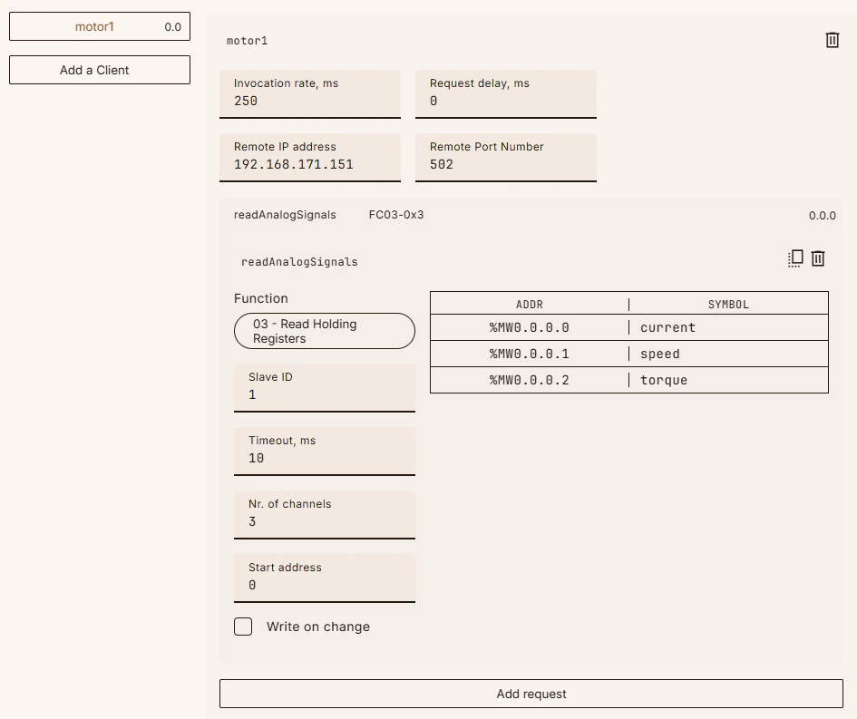
| Field Name | Explanation |
|---|---|
| Invocation rate, ms | The interval in milliseconds between sending of requests. |
| Request delay, ms | The delay in milliseconds between the end of the previous response and the beginning of the next request to be sent, if needed. |
| Remote IP address | The IP address of the Modbus TCP server. |
| Remote port number | The port number that the Modbus TCP server is listening on, usually 502 or 1502. |
- FC01: Read Coils
- FC02: Read Input Discretes
- FC03: Read Holding Registers
- FC04: Read Input Registers
- FC05: Write Single Coil
- FC06: Write Single Register
- FC15: Write Multiple Coils
- FC16: Write Multiple Registers
| Field Name | Explanation |
|---|---|
| Slave ID | The slave ID (unit ID) of the device that will receive the requests. |
| Timeout, ms | The request timeout in milliseconds, i.e., the time allowed for the server to respond before the client gives up. |
| Number of channels | The number of registers to be read/written. |
| Start address | This is a 0-based offset from the first address of the corresponding data area. Example: Holding registers start at 40001, so a start address of 5 corresponds to register 40001 + 5 = 40006. |
| Write on change | Applies to function codes 5, 6, 15, and 16 only. If checked, requests will only be sent when the linked variables change. Otherwise, they’ll be sent as per the invocation rate as usual. |